Software for Wall Hugger Action:
Part 5 Software Makes it Go!
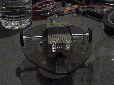
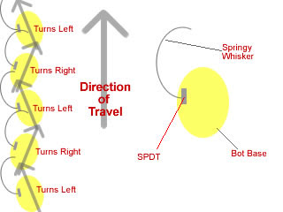
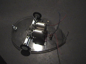
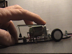
This is the basic wall follower software... This software makes the bot turn left to hug the wall, with the values given, you will find MouseBot is FUN!!!
There are routines for left and right turn and the object detection operation as well as a speaker (squeaker) for your mouse. I'm still waiting for the piezo-speaker to come in the mail... I had one, but it was already in use. By using pin0 as a multi-purpose pin, we can add a speaker, which gives us some noise when downloading, but allows the little picAxe m8 to serve of the brains for the BEAM style "Wall Hugging Mouse" conversion to BEAM with BRAINS...
I know you'll want to do crazy things with your bot, so have at it, put the link to your MouseBot with Brains video so we can all see it...
' ------------------------------------------------------------
' BEAM bot Brains
'
' Basic Operation of mouse as "wall hugger" just like original
' Except for:
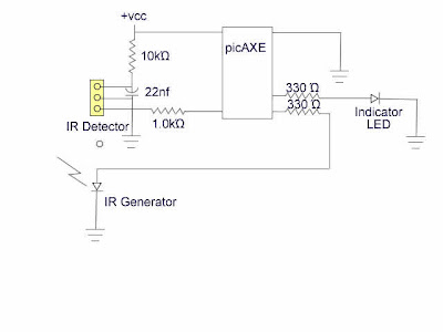
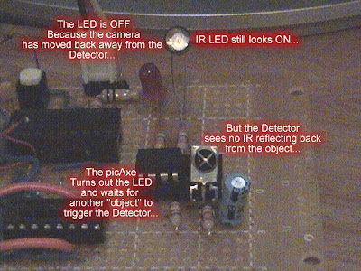
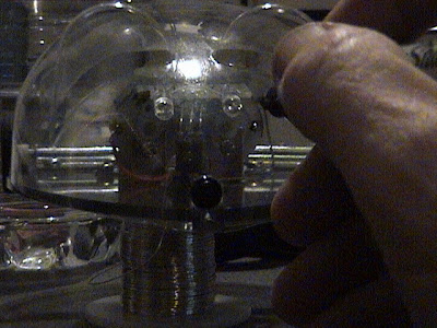
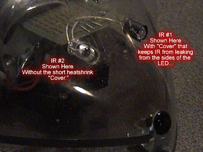
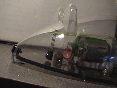
' IR detector "whiskers" lets the mouse find it's way
' Follows walls without physically touching
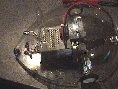
' Still has basic motor control with microcontroller picAxe m8
' Copyright 2008 Jim Huffman
' Permission granted to experimenters to use all or part
' Note copyrighted material frequency chart at the end
' Basic Interpreter Directives
#picaxe 08m
' Microprocessor pinouts and layouts 08m
symbol LED = 0 '(leg 7) Serout/LED
symbol rightDrv = 1 '(leg 6) High = motor on
symbol pout = 2 '(leg 5) PWMout2
symbol IRin = 3 '(leg 4) Input only pin3
symbol leftDrv = 4 '(leg 3) High = motor on
' (leg 1 Vdd, leg 8 = Vss, leg 2 = Serial In)
symbol spkr = 0 'extra symbol, speaker drive
' Variables used in program
symbol xCnt = b0
symbol rightDrvFlag = b1
symbol leftDrvFlag = b2
symbol objDetFlag = b3
symbol rightDrvTime = b4
symbol leftDrvTime = b5
init: ' Initialize chip so OK with low Vcc supply
disablebod
setfreq m4
' flash LED
high LED
pause 1000
low LED
pause 1000 'wait for Panic resets, etc...
' initialize variables
leftdrvTime = 120 ' Permits balancing forward motion
rightDrvTime = 100 ' allows motor speed balancing
low rightDrvFlag, leftDrvFlag, objDetFlag, xCnt ' initialize values
' Main driving loop avoids walls
main:
gosub driveforward
pause 10
goto main
' Move forward one time after the other - makes mouse wiggle
driveforward:
gosub objDetect 'makes 1/2 wiggle unless there is an object
' the other 1/2 wiggle even if there is a wall
high leftDrv
pause leftDrvTime
low rightDrv,leftDrv 'stop\
pause 10
return
' Driving commands (turns) stick in the appropriate spots
turnRight:
high rightDrv
pause rightDrvTime
low rightDrv,leftDrv 'stop
return
turnLeft:
high leftDrv
pause leftDrvTime
low rightDrv,leftDrv 'stop
return
' If an object is "sniffed out" then set objDetFlag high
objDetect:
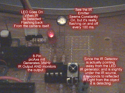
pwmout pout, 22, 50 '25, 52 ' 26 usec period = 38.4 kHz
pause 3 ' Begins continuous output PWM
if pin3 = 0 then ' Object Detected
pause 3
pwmout pout, 0, 0 ' stop the continuous pulse output
else
' 1/2 wiggle (unless there's a wall)
high rightDrv
pause rightDrvTime
low rightDrv,leftDrv 'stop
pause 10
endif
pwmout pout, 0, 50 ' stop the continuous pulse output
return
MakeSound: ' fast-beep make a squeek...
setfreq m8 'kick into high-speed mode
for xCnt = 100 to 130
pulsout spkr, xCnt
next xCnt
low spkr
setfreq m4
return
' Chart of frequencies courtesy of PHAnderson...
'------------------------------------------------
' From IR_1.Bas
'
' copyright, Peter H Anderson, Baltimore, MD, May, '04
'
#rem ' PWMOut pout, Period, DutyCycles
PWMOut pout, 25, 52 ' 38.4 kHz
PWMOut pout, 24, 50 ' 40.0 kHz
PWMOut pout, 23, 48 ' 41.6 kHz
PWMOut pout, 22, 46 ' 43.5 kHz
PWMOut pout, 21, 44 ' 45.5 kHz
PWMOut pout, 20, 42 ' 47.6 kHz
PWMOut pout, 19, 40 ' 50.0 kHz
PWMOut pout, 18, 38 ' 52.6 kHz
PWMOut pout, 17, 36 ' 55.5 kHz
PWMOut pout, 16, 34 ' 58.8 kHz
#endrem