MouseBot Electronic Motor Control
Part 3 Wall Follower Mouse 'Bot Transformation
Let's put the ram in ramalamadingdong!
First Ya Need a Motor... Pretty much any-old hobby motor will work here. In Mousebot, we have not just one motor, but two... That means, of course, we can steer mousebot... That's how he works in the first place, using two motors, one that steers "into" the wall, and other that pulls mousebot forward into the open spaces...
We have our mousebot whiskers ready to go now (see blog) with a cool object avoidance system overseen by a picAxe m8 8-pin processor. By judicious re-use of pin0 for running the redLED in MouseBot's head and a piezo noise maker, we have two pins left over...
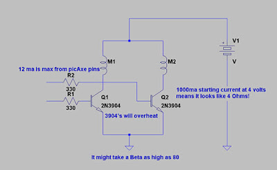
That means we could use one pin to turn on one motor and with two pins, this is most promising for MouseBot... Let me show you:
 |
| From Mouse Bot Tra... |
MouseBot's simple driver will not be able to back up, but, MouseBot can stop on a dime, and can turn on it's motors independently of each other, like this:
' System resources 08m pinouts and layoutsSo the software controls the MouseBot's motors as it runs around... As shown in the test Run listing above. There are lot of things wrong with this piece of code, it makes no effort to make the motor run with any efficiency or multiprocess the motor and the picAxe simply by using an interrupt driven system. Those improvements will come later, the whole idea here was to add a picAxe to the Wall Following Mouse Robot. Since we have enough pins to do the object detection, it was decided to use the two extra pins to control MouseBot.
symbol LED = 0 '(leg 7) Serout/LED
symbol M1 = 1 '(leg 6)ADC1
symbol pout = 2 '(leg 5)ADC2,PWMout2
symbol IRin = 3 '(leg 4)
symbol M2 = 4 '(leg 3)ADC4
'(leg 1 Vdd, leg 8 = Vss, leg 2 = Serial In)
symbol xCnt = b0
'
high LED
pause 1000
Main:
low LED
pwmout pout, 22, 50 '25, 52 ' 26 usec period = 38.4 kHz
' for 40 kHz, use pwm IRsignal, 24, 50
' MAX Range about 4-5 ft 26, 50
' 3ft 27, 50
' 6" (closeup) 18, 40
' 2" (eXtreme closeup) 10, 40
Pause 3 ' Begins continuous output PWM
if pin3 = 0 then ' Object Detected
high LED
low M2
pause 1000
' go do things...
endif
gosub driveAround
pwm pout, 00, 00 ' turn off the PWM
Pause 100
GoTo Main
driveAround:
high M1,M2
pause 100
return
Let's add the transistors shown like in the conceptual schematic shown... Then the whole Mouse Bot project is done, though ol' Mousey will never go backwards. Most mice I've dealt with ran forwards anyway, of course that could be because a pack of humans with brooms and loud screaming voices were after them...
Finished!
| From Mouse Bot Tra... |
Closeup:
| From Mouse Bot Tra... |
Hardware Finished... Of course, the software needs fixin' I'll get to that later, I can usually cram a few hours of programming in more easily than a few hours with the hardware. And, software is really all that's left to extract the most fun from the MouseBot...
Mouse Bot Rules!
If you try this test, you will notice MouseBot gives up the ghost very quickly... This effect is caused by driving the 2N3904's too hard... Don't run it this way other than short tests, or with the body off the robot... You'll melt MouseBot's head!
But wait! All is not lost! We have the next (and hopefully, final) episode in the transformation of the wall following robotic mouse: Next Time... A non-melting drive system....
No comments:
Post a Comment